I’d like to start compiling information about the screens people are using. Please visit this page before you go, where I also have a sketch that attempts to read the LCDs driver code without any additional libraries.
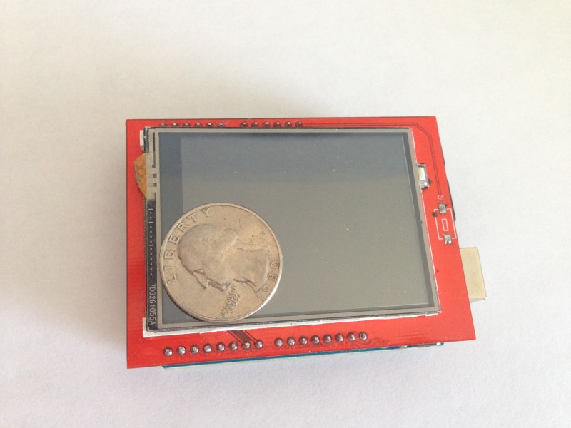
My First Shield
I was looking for some type of touch screen for the Arduino when I ran across this little gem on eBay. I was hoping to avoid a shield, but for only $8.14 with free shipping (from China), I decided to give it a shot. It ended up taking me longer than the advertised 10 minutes to get it working, but the more I’ve played with it, the more I think I’m starting to like it.
Libraries Included (Kind of)
The shield came packed with one of those tiny CD ROM discs with a few different RAR files on it. The one with “arduino-UNO” in the name seemed like the most likely candidate, so I opened it up and started poking around.
 After some trial and error, including finding the correct library, changing library names, altering include file references, etc., I managed to get something on the screen. I made many small tweaks to the LCD library to make my life a little easier (see below), but the many references to Adafruit in the code led me to give their web site a look. There I found a library for a 2.8″ touch screen that looks very similar to this one. I’m not sure the code in their libraries will work without modification, but they may be worth taking a look at.
Picture Quality
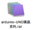
I didn’t have very high expectations in terms of picture quality, so I wasn’t disappointed. Overall, I would rate it as good enough for the average hobby project. While you won’t be floored by the rich colors, in the context of price and features, it’s more than sufficient.
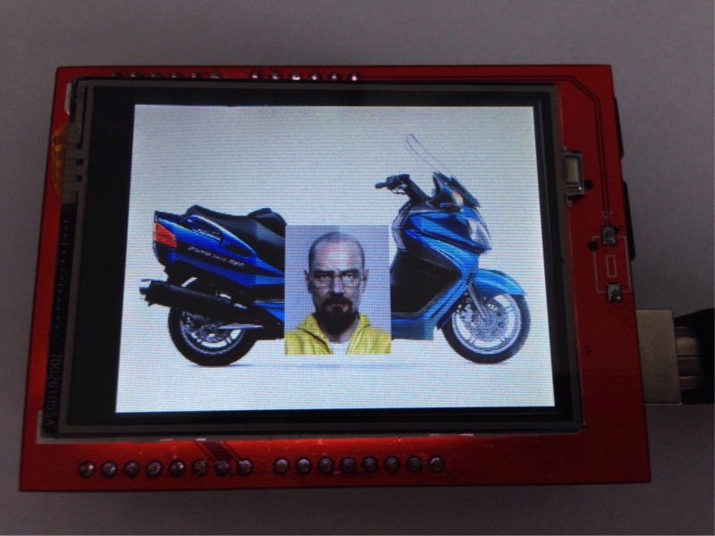
Compare the original image below to the 16-bit screen representation to its right. While the picture of the LCD screen doesn’t really do it justice, it should give you an idea of what you’ll see. The first thing that will likely draw your attention about the screen image is the very noticeable banding. This becomes less apparent with line drawings using a simpler color palette, but it is very visible when viewing bitmaps or filling the screen with a solid color.

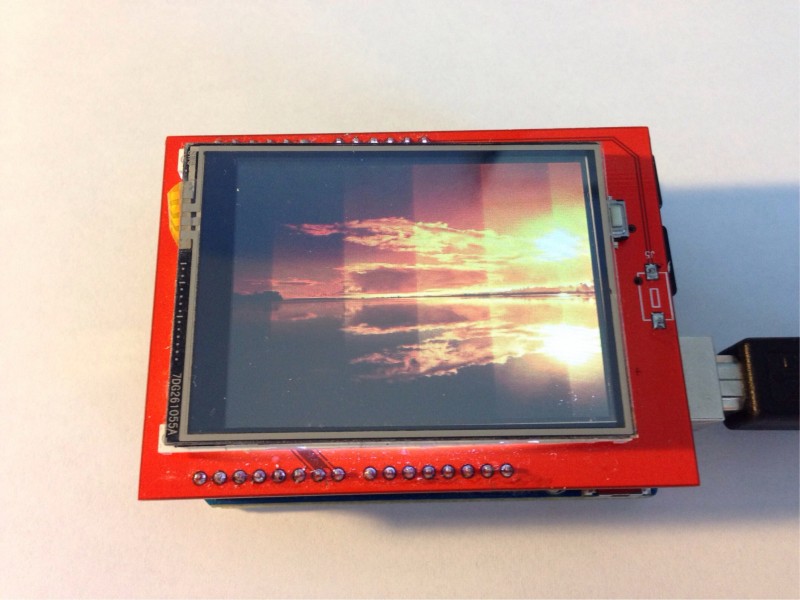
SD Card Slot
The shield comes equipped with a micro SD card slot, which I really had no real intention of using when I bought it. My curiosity quickly took over, however, and I tried to run some of the sample code. Unfortunately, I didn’t meet with any success during my initial attempts to get it working and threw in the towel completely after pushing a bit too hard on the card as I inserted it, breaking the connector off the board.
The next day, I decided to give it another go, so I got out my soldering iron and did my best to reattach the connector, despite the miniature nature of the surface mount pins. I made sure to get plenty of solder on the four legs to keep it firmly attached to the board, then did a less than stellar job of getting a bit of solder on the tiny pins.
I took a quick glance with a magnifying glass, and it didn’t appear that I had left any shorted pins, so I tried the sample code again. Much to my surprise, it worked, and before long I was looking at my own bitmap images on my Arduino screen.
Using the Shield
General
I’m still not sure exactly what driver chip my LCD is using. The libraries included with the unit expand into a directory called “arduino-9320”. I originally took this to mean that it used the ILI9320 chip and started working from the data sheet I found here to expand functionality as needed. However, some of the sample code does a driver check before proceeding, as follows:
 // find the TFT display
 uint16_t identifier = tft.readRegister(0x0);
 if (identifier == 0x9325) {
    Serial.println("Found ILI9325");
 } else if (identifier == 0x9328) {
    Serial.println("Found ILI9328");
 } else {
    Serial.print("Unknown driver chip ");
    Serial.println(identifier, HEX);
    while (1);
 }
According to the ILI9320 data sheet, register 0x0 will return 0x9320. On my board, I get a reading of 0xC505. I haven’t run into anything that hasn’t worked thus far, so I haven’t done any further research. Disabling the check is good enough for what I’m doing at this point.
I have made some modifications to the library included with the board, and I’ll include my files below. It wasn’t until after I’d started monkeying with things and noticing references to Adafruit in the code, that I realized there may be better options already out there. Whether or not they work with this screen is something I have yet to determine.
Adafruit libraries here: http://learn.adafruit.com/2-8-tft-touch-shield/overview
Displaying Graphics
The TFT library includes functions for drawing lines, rectangles, rounded rectangles, circles and triangles, all of which can be filled or outlined. There is example code that cycles through various screen patterns using each.
After I got the SD card reader working, I spent some time concentrating on loading bitmaps. The sample code that comes with the library has a few examples that load 24-bit bitmap files from the SD card and display them on the screen in various rotations. These samples didn’t work correctly until I modified the code to use the setPixel method, which resulted in a very slow display time but worked in all screen rotations.
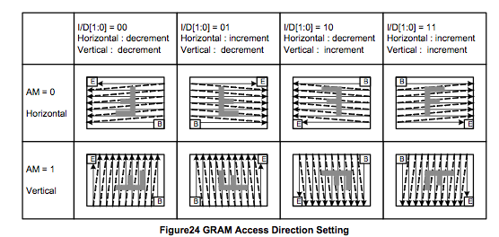
The writeData method that was originally being invoked simply writes to the display’s graphics memory, which is a good thing for speed. However, this method was not taking screen rotation into account. Studying the data sheet, I found that “GRAM Access Direction” can be altered such that after a writeData call, the next write address will be properly calculated based on the current rotation. With that information, I modified the setRotation method to also change the GRAM access direction.
This new setRotation method fixed the bitmap sample code to some extent and sped things up considerably. Unfortunately, it was still taking 2.8 seconds to load and display a 320×200 24-bit bitmap. It was time to get serious.
The firs thing I did was switch away from the 24-bit bitmap format. The display uses a 16-bit RGB format (R5G6B5), so it makes more sense to do that transformation somewhere other than the Arduino if you’re just worried about getting it onto the screen as quickly as possible. Furthermore, the standard Windows bitmap file is stored in a bottom-up format, which adds a little complexity to the direct write method. So, I wrote a little utility to convert my bitmap files to a 16-bit, top-down format that could be directly loaded into the LCD’s GRAM. You can find that utility here.
Moving to the 16-bit format had a huge impact on performance, though I didn’t think to take any timings in this state, as I wasn’t quite done. My next step was to simplify loading by getting rid of the position calculations required for bitmaps that didn’t extend the entire width of the screen. The data sheet provides details about creating a window within the screen, which you can specify the dimensions of. Combining this window setting with the GRAM access direction settings mentioned above, it is possible to just send the pixel information in bulk and allow the LCD driver chip handle the wrapping.
The end result is fast, loading and displaying a 320×240 scooter image in 1.3 seconds and the smaller picture over the top in 129 milliseconds. I’ve since been experimenting with the sdfatlib library for SD card access, and the results have improved even further, bringing load/display time to 1.048 seconds. I was looking more for a smaller footprint, but I’ll take the the speed as well.
Arduino Code
void displayBitmap(int x, int y)
{
  uint16_t bx, ex, by, ey;
  uint32_t time = millis();

  // Raw pixel data starts at position 8
  bmpFile.seek(8);

  // Save the current viewport settings and set
  tft.getViewport(&bx, &ex, &by, &ey);
  tft.setViewport(x, y, x + bmpWidth - 1, y + bmpHeight - 1);
  tft.goTo(x, y);

  // Bulk write data to LCD, loadBitmapData is a callback to refill buffer
  int bytesRead = loadBitmapData(NULL);
  tft.bulkWrite( (uint16_t *) picBuffer, bytesRead, loadBitmapData, NULL);

  // Leave the viewport like we found it
  tft.setViewport(bx, ex, by, ey);

  Serial.print("Total time: ");
  Serial.println(millis() - time, DEC);

}
TFT Driver Code Addition
// Writes 16-bit data in bulk, using callback to get more
void TFTLCD::bulkWrite(uint16_t *data, uint16_t bufferSize, uint16_t (*getNextValues)(void *), void *userData)
{
	*portOutputRegister(csport) &= ~cspin;
	*portOutputRegister(cdport) |= cdpin;
	*portOutputRegister(rdport) |= rdpin;
	*portOutputRegister(wrport) |= wrpin;

	setWriteDir();
	while( bufferSize )
	{
		for(uint16_t i=0; i < bufferSize; i++)
		{
			writeData_unsafe(data[i]);
		}
		bufferSize = getNextValues(userData);
	}
	*portOutputRegister(csport) |= cspin;
}
Touch Screen
The display and touch screen features were what I was really looking for from this LCD, though I became somewhat sidetracked by the bitmap examples. The touch screen example software ran pretty much without a hitch from the beginning using the pin settings for the shield. Essentially, you get two coordinates (X and Y) back from the screen, plus a Z, which indicates the pressure being applied. Those coordinates coincide with the LCD’s default rotation, which is with the Arduino’s USB plug on top in this case, so you’ll have to adjust those for yourself.
#include "TouchScreen.h"

// These are the pins for the shield!
#define YP A1  // must be an analog pin, use "An" notation!
#define XM A2  // must be an analog pin, use "An" notation!
#define YM 7   // can be a digital pin
#define XP 6   // can be a digital pin

#define MINPRESSURE 10
#define MAXPRESSURE 1000

// For better pressure precision, we need to know the resistance
// between X+ and X- Use any multimeter to read it
// For the one we're using, its 300 ohms across the X plate
TouchScreen ts = TouchScreen(XP, YP, XM, YM, 300);
The one potential area for trouble is the fact that the touch screen shares pins with the LCD. So, if you invoke methods from the touch screen library, then make calls to the LCD library, you may get unexpected results, as the touch screen library doesn’t always leave things in the right state, and the LCD library doesn’t put them in the right state before it does its work. The newer Adafruit libraries may account for this better than the ones I’m using, but I’ve worked around it for now.
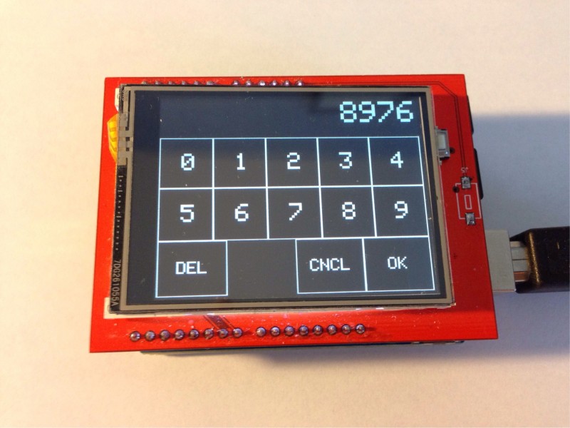
At this point, I’ve done a little bit of experimentation with the touch screen, mainly in the form of a numeric input form, as shown below. I’ve tried to do some coordinate calibration based on actual readings, but it seems like I get some occasional outlying values that throw a wrench in things. So, I’ve pretty much stuck with the default values from the sample code and haven’t had any problems getting very reliable finger positions.
A question was brought up in the comments regarding debouncing the touchscreen input to avoid getting repeat presses. Trying to reliably detect when a user presses and removes a finger from the screen in all cases has proven to be more difficult than I thought. This is the code I’ve written so far, which does a decent job of registering intentional finger presses with minimal duplication. When I have more time, I’ll see if I can improve it a bit.
Point getPressPosition()
{

   Point p, q;
   int upCount = 0;

   // Wait for screen press
   do
   {
      q = ts.getPoint();
      delay(10);
   } while( q.z < MINPRESSURE || q.z > MAXPRESSURE );

   // Save initial touch point
   p.x = q.x; p.y = q.y; p.z = q.z;

   // Wait for finger to come up
   do
   {
      q = ts.getPoint();
      if ( q.z < MINPRESSURE || q.z > MAXPRESSURE  )
      {
         upCount++;
      }
      else
      {
         upCount = 0;
         p.x = q.x; p.y = q.y; p.z = q.z;
      }

      delay(10);             // Try varying this delay

   } while( upCount < 10 );  // and this count for different results.

   p.x = map(p.x, tsMinX, tsMaxX, 0, 239);
   p.y = map(p.y, tsMinY, tsMaxY, 0, 319);

   // I've been focused on rotation 3, with the USB connector on the right-hand side
   // so, you'll have to add your own code here.
   switch( ROTATION )
   {
      case 3:
         swap(p.x, p.y);
         p.x = (320 - p.x);
         break;
   }

   // Clean up pin modes for LCD
   pinMode(XM, OUTPUT);
   digitalWrite(XM, LOW);
   pinMode(YP, OUTPUT);
   digitalWrite(YP, HIGH);
   pinMode(YM, OUTPUT);
   digitalWrite(YM, LOW);
   pinMode(XP, OUTPUT);
   digitalWrite(XP, HIGH);

   return p;
}
SD Card
As I mentioned, the SD card wasn’t something I was necessarily looking for from this shield, but it has proven to be a blessing. It works with the standard Arduino SD library, and I’ve also tried the sdfatlib with great results. The cable select should be set to pin 10, and after that, you’re ready to go. There is an example called “listfiles” that spits out a directory listing, which is great for both testing that the card works, and as a reminder that you’re limited abbreviated file names that turn a name like “BURG_BLUE.BMP” into “BURG_B~1.BMP”.
Source Code
I have attached the TFTLCD libraries with the modifications I’ve made for rotation and positioning reliability as well as the bulk data load function I’m using for displaying bitmaps. Sample sketches are also included and should work with this LCD without modification.
There seem to be variants of this shield that look the same or similar but function differently. Many users have had issues with reversed text and coordinate flipping using the same library I originally provided. In the comments, Mike McCauley added a link to a patched version of the library that may fix reverse coordinate issues. I have now added his patch into my library to avoid further confusion.
Click here to download: TFTLCD.zip
If your coordinates appear to be reversed, uncomment either or both of the lines below in TFTLCD.cpp and try again.
//#define INVERT_X
//#define INVERT_Y
Thank you to everyone who has participated in the comments and helped find solutions to make this board useable for everyone.
Update – June 26, 2014
I was able to get this screen working as a shield with an Arduino Mega 2650 as well. I posted an article with an updated source file. Until I get some feedback, I’ll consider it experimental. The article is here.
Pingback: Bitmap Converter for Arduino LCD | misc.ws
Hey Justin,
How did you go with the touchscreen code? I have the same shield but only get double characters when I press a number (doing the touch numeric keyboard thing as well).
Cheers,
Darren.
Great question, Darren. I’ve been struggling with that one a bit myself. I updated the article with the code I’ve written up to this point, and if I come up with something even more reliable, I’ll update it again. I’d like to get it to the point where I can reliably tell exactly when the user presses and releases the screen without duplicates.
Hey Justin Great post….
I got the same lcd and my lcd co-ordinates appear reversed.
I uncommented either and both of
//#define INVERT_X
//#define INVERT_Y these lines but it didn’t work.
It seems changing anything in TFTLCD.cpp file doesn’t affect the code. Please help me . I am stuck at the same point from two weeks. 🙁
If you are having problems with mirroring or reversed characters / touch coordinates you should check out this tutorial:
http://www.instructables.com/id/UNO-R3-28-TFT-Touch-Screen-With-SD-Card-Socket-for/
There are code examples using AdaFruit libraries. There is a number pad tutorial that discusses the mirror issue and reversed characters.
Essentially, you need to make sure you set the rotation even if you are using the default rotation. Just add tft. setRotation(0); to your setup routine (if using default rotation).
For the reversing of coordinates, you need to make sure the raw coordinates are correctly transposed; from tft.width() and tft.height() to screen coordinates like 320×240 (or whatever your model supports).
For example, the raw coordinates of a touch might be 510x 420y which might translate to something like 240×160.
Hi,
What do I need to compile the bmp2lcd utility in Windows? Can I use Atmel Studio or do I need another compiler? I want to try your 16 bit bmp method but don’t know exactly what to compile the source with.
Thanks in advance.
Yeah, that looks like the problem. I’ve run a serial port test on it and it doesn’t reliably hold the pressure level in the Z portion of the pointer, dropping back to 0 in between readings. Certainly makes it difficult to detect a press and perform some form of Schmitt trigger on it to stop the double-striking.
Cheers, and thanks for the reply!
Darren.
I took another look at the TouchScreen.cpp file in the libraries folder. There I found this, which may describe what you’re talking about, inside of the getPoint method.
#if NUMSAMPLES == 2
if (samples[0] != samples[1]) { valid = 0; }
#endif
…
…
if (! valid) {
z = 0;
}
I tried changing the NUMSAMPLES to 3, and I got perfect results when used in conjunction with the code I posted above. I’ll play more, but it looks like additional sampling or simply not disregarding the z if back-to-back samples match might be a step toward the fix.
The problem is that the getPoint routine returns z=0 for two different cases: when pressure is zero and when their oversampling algorithm finds values that it considers invalid. A solution I’ve used is to alter lines around 155 in TouchScreen.cpp from
if (! valid && z > 0) {
z = 0;
}
to
if (! valid && z > 0) {
z = -1;
}
This returns z=0 when not pressed (i.e. finger up, and z=-1 when the oversampling routine detects invalid values. You can test specifically for z==0 in the sketch to detect the finger lifted condition without it being spuriously triggered by the oversampling routine while the finger is still down.
Hi Justin, thanks for your work on this – I plan to feature it in a story I’m writing for APC magazine (apcmag.com) shortly.
Cheers,
Darren.
I got Unknown driver chip C0C0, on same shield. What can be the difference?
Wow. There’s part of me that wonders if it’s even reading the register correctly. I’m playing with the Adafruit library, and that’s returning 0x0 for the ID, though I’ve gotten it to produce graphics on the screen by forcing it to initialize properly.
Hi! Your work here helped me a lot! Right now I’m modifying the Adafruit library to work with this shield, I replaced part of the code on the Adafruits with the “_regValues[]” and the “initScreen” from the CD’s library and it worked! But I have the problem that X axis is mirrored, so the characters look backwards. If you have made something to solve this orientation problem, it would help me a lot!
My apologies about my English!
First, your English is great. I ran into the same problem with the Adafruit library when I tried it, but I haven’t had a chance to get back in and see what can be done to fix the backwards problem. Once the holiday season has passed and I get back to normal life, I’ll take another look and update you.
I just picked up this same lcd. I also noticed that text is upside down and backwards. I discovered this blog (which is much appreciated, btw) because I was googling “spfd5408 arduino backwards”. However, I’m not certain that our displays are identical. Mine has some printed icons on the ‘bottom’ and is intended to be used in a phone, in a portrait orientation. I’m sure you would have mentioned if the text in the example program didn’t appear correct.
Any hoo…
I started thinking about how the text in the graphic demo is displaying on MY screen. X=0 and Y=0 is actually the bottom left (when viewed in portrait). But I would prefer that the ‘origin’ be at the top left and the display be viewed in a landscape orientation. So I looked at the code in TFTLCD.cpp for drawing characters and strings and swapped X and Y by adding this line (as the first line) to drawString() and drawChar():
uint16_t t = x;x=y;y=t;
That works, but the fonts are sideways. So I then looked at the hex in glcdfont.cpp. For a moment, but only a moment, I considered that I really needed completely different font codes. The I looked more closely at drawChar() and just swapped the counters used to walk through the bits of each hex code…
void TFTLCD::drawChar(uint16_t x, uint16_t y, char c,
uint16_t color, uint8_t size) {
uint16_t t = x;x=y;y=t;//xy
for (uint8_t i =0; i<5; i++ ) {
uint8_t line = pgm_read_byte(font+(c*5)+i);
for (uint8_t j = 0; j>= 1;
}
}
}
@Sebastion, Not sure if this is the same thing you’re talking about, but thought I’d mention it since this blog is only a couple months old.
Thank you, Brian. I still haven’t had a chance to try it, but it sounds like you’ve got it figured out.
@Brian, I too just purchased the same shield… former phone button silkscreen on the touchscreen and inverted touch orientation and backwards text.
Unfortunately, my coding skills are still in their infancy and I am unclear on implementing the changes you suggest… I know how to edit the files, just not the precise location of any changes and /or additions to the code. I took a few stabs at it, but just get compiling errors. Any chance on further clarification of the exact changes required in the TFTLCD.ccp, and/or updated libraries?
Thanks!
I’d like to say that your way did not work in my case (mirrored letters), but i have dealt with it by changing the bit rotation. In order to do it, you need to modify the following lines in drawChar function:
if (line & 0x1) { you change to if (line & 0x80) {
and at the bottom:
line >>= 1; to line <<= 1;
good luck
FYI – based on your above comments the phone icons. BTW Im not using this code but
I Purchase 3 displays from a an offshore vendor. Two with the phone icons on the bottom one without.
I eventually was able to get the one without icons working but not the 2 with icons yet (they just white screen).
I thing must be different even if the vendor says they are not.
Ooops. My drawChar() instance method didn’t make it. I swapped the ‘i’ and ‘j’ loop counters in the calls to drawPixel() and fillRect(), so that ‘j’ was used to modify the x coordinate and ‘i’ was used to modify the y coordinate.
Brian,
I found the line in the file but it will not compile.
void drawChar(uint16_t x, uint16_t y, char c, uint16_t color, uint8_t s = 1);
Seems a few too many closing brackets at the end. Do you have a chunk of code I can just drop in? If you could post it here, I’d appreciate it.
HI Justin;
I have been downloaded your library in rar format. It compiles satisfactorily problem is that SD Card is not working properly. The message shown by Arduino serial port monitor is “SD Card initilization failed”. Although I selected proper chip select of SD Card. Kindly, tell me how can I achieve this goal. Your prompt reply is highly appreciated.
Thanks and regards,
Muhammad Farrukh Ali.
When I received my LCD, the SD card connector didn’t seem to be very well attached, and it didn’t work until I re-soldered it to the board.
Hi,
I have the very same display (2 of them), I’ve tried to download your library but my display stay stubbornly blank… I’ve tried on arduino uno, a clone of uno… But nothingh !
I start supposing that I’ve got a bad lot, I got chinese “chep as welll…”
Apart from your modified library what I should use ? Also any advice about the arduino suite ? I’ve used several but no way.
Thanks for your help !
Alex.
If your Arduino is working for everything else, you might try the Adafruit code. Other than that, it’s hard to say. I haven’t really done too much with the Arduino yet, but everything I’ve tried so far seems to be working without much of a hassle. I’ve got two boards, one that is a real Arduino, and one that I assume must be a clone based on the fact that I got it on eBay for a fraction of the price.
Thanks for your help, I’ve tried your library and adafruit but I was not lucky. Perhaps I should start from scratch, or perhaps I was plainly cheated !
BTW, which version of the compiler you used ?
Alex.
Hello Justin,
I really thank you for your really great work, i’m quite new at the Arduino world, so it’s impossible for me to make this type of things 😀 . I have the same shield/screen, and your library works really well, but there are stil 2 problems:
– I read in some comments above that some persons have the text upside down, and i have the same problem. As i’m new, i couldn’t understand what’s the solution, so could you please explain a bit how to solve it?
– I didn’t understand how to use the touchscreen. I’m using the Arduino Mega2560, so i’m using the pins a)-A4 and 22-29. which pins are used by the touchscreen, and how do I use it…? i saw that it shares pins with the LCD, but even if you explained somehow how to use it, i’m not an expert and can’t use it 😛
Thank you very much again for this awesome library and I hope for your helpful reply,
Pierre LACLAU, France.
P.S.: Do you have any tutorial or something like that ? i think it’d be really handy for persons like me !
Sorry for double post (and very long comment), but I found the solution for the text orientation issue. Still not for the touchscreen, who know i’ll maybe find it ?
For those like me who don’t understand the explanations in the comments above, let me do a little and simple “tutorial”:
1. Go at the library folder, named TFTLCD;
2. Open the file named “TFTLCD.cpp” with any text editor;
3. Search for the function “void TFTLCD::drawChar(uint16_t x, uint16_t y, char c, uint16_t color, uint8_t size) { […]”;
4. Delete these lines:
void TFTLCD::drawChar(uint16_t x, uint16_t y, char c,
uint16_t color, uint8_t size) {
for (uint8_t i =0; i<5; i++ ) {
uint8_t line = pgm_read_byte(font+(c*5)+i);
for (uint8_t j = 0; j>= 1;
}
}
}
5. Now there are two cases: if the text is just upside-down, go to step 5.a.
if the text is just sideways, go to step 5.b.
if the text is both upside-down AND sideways, then go to step 5.c.
5.a Paste at the same place the lines:
void TFTLCD::drawChar(uint16_t x, uint16_t y, char c,
uint16_t color, uint8_t size) {
for (uint8_t i =0; i<5; i++ ) {
uint8_t line = pgm_read_byte(font+(c*5)+i);
for (uint8_t j = 0; j>= 1;
}
}
}
5.b Paste at the same place the lines:
void TFTLCD::drawChar(uint16_t x, uint16_t y, char c,
uint16_t color, uint8_t size) {
uint16_t t = x;x=y;y=t;
for (uint8_t i =0; i<5; i++ ) {
uint8_t line = pgm_read_byte(font+(c*5)+i);
for (uint8_t j = 0; j>= 1;
}
}
}
5.c Paste at the same place the lines:
void TFTLCD::drawChar(uint16_t x, uint16_t y, char c,
uint16_t color, uint8_t size) {
uint16_t t = x;x=y;y=t;
for (uint8_t i =0; i<5; i++ ) {
uint8_t line = pgm_read_byte(font+(c*5)+i);
for (uint8_t j = 0; j>= 1;
}
}
}
————————————————————————————–
I hope it is clear, and hope it’ll be useful for some of you. Now it works fine for me, this library is really perfect!
For the touchscreen library, i still don’t get it… 😀
Thanks in advance for your future reply, Justin! (and maybe another person?)
the tftlcd.cpp that i have , that come in the rar file from this site look different
// draw a character
void TFTLCD::drawChar(uint16_t x, uint16_t y, char c,
uint16_t color, uint8_t size) {
for (uint8_t i =0; i<5; i++ ) {
uint8_t line = pgm_read_byte(font+(c*5)+i);
for (uint8_t j = 0; j>= 1;
}
}
}
what line do i have to change for upside-down AND sideways
sorry for double post wrong cut and paste
// draw a character
void TFTLCD::drawChar(uint16_t x, uint16_t y, char c,
uint16_t color, uint8_t size) {
for (uint8_t i =0; i<5; i++ ) {
uint8_t line = pgm_read_byte(font+(c*5)+i);
for (uint8_t j = 0; j>= 1;
}
}
}
Well, i don’t know why you have another code, the best solution i’d give you is downloading the changes made by Mike McCauley (the comment just below) and testing it. It personally solved all my problems, maybe it’ll be useful for you too ?
If you still have problems, just comment again and i’ll see if I can do something..!
Thanks for this library.
I too got some of the cheap LCD screens marked with http://www.mcufriend.com, and I too get reversed text.
But further tests, such as the included tftpaint show that the Y coordinates are reversed.
Further investigation shows that on my devices the direction of the Y coordinates is reversed to that expected by the library.
So, its not sufficient to just alter drawText as described above, but to make some similar changes to the low-level drawing routines.
I have made appropriate changes to the library to suit my device, in a modular way so it will now support devices with and without X and/or Y coordinate flipping. Note: this is not the same issue as the orientation feature added by Pierre. I have also included the TouchScreen code used by the examples.
All the included examples now compile and run correctly out of the box.
http://www.airspayce.com/mikem/TFTLCD-mikem.zip
Thanks man, I just got this lcd yesterday and tried to make this work for few hours :D, but unfortunately when it started to work the image was mirrored. But the TouchScreen files are corrupted, the program won’t compile when they are in the library folder, there’s no problem after removing them so maaaaany thanks :).
Thank you very much Mike, your changes solved all my problems ! 😉 now I can use this LCD to control my whole bedroom !
can you help me . I’m newest . I got the same TLC 2.7 but I dont know how make it work .. Thanks you
Thank you very much, Mike. I added an update to the article making your solution easier to find.
Justin, can you kindly send me the example of the keypad test you have done, I would be really interested in seeing how you have acheived this.
Big thanks
Daniel
Hey, Daniel. I had a project in mind for this screen, but too many other things got in the way, and I never finished working on it. My keypad test can be downloaded here.
hey! i have downloaded justin’s as well as mike’s code. in justin’s code there is a pin LCD_CD defined on the pin A2, but theres no such pin on the LCD, where does it go exactly? can someone please help me ASAP? 🙁 i am using the exact shield that justin has put up on the blog.
I have this same problem too.
Hi, I have got this screens today 2 of them, but after loading test sketch, screen just blink and does not do anything else. I’m running it on Arduino Mega with modified TFTLCD.cpp from this topic: http://misc.ws/2014/06/26/touch-screen-on-the-arduino-mega-2560/, what could be wrong?
Hallo Mike,
I do get the following error:
“C:\Users\Documents\Arduino\libraries\TFTLCD\glcdfont.c:9:23: error: variable ‘font’ must be const in order to be put into read-only section by means of ‘__attribute__((progmem))’
static unsigned char font[] PROGMEM = {
^
exit status 1
Fehler beim Kompilieren für das Board Arduino/Genuino Uno.
Do you happen to have an idea on how to resolve it!
Regards,
Robert Makanga
Thanks to Justin and Mike.
I got here from the APC article, after buying a few of the screens to try.
Mine look like the one in Justin’s photo, but exhibited the mirror-imaged text in the graphics test sketch.
Mike’s library fixed that. Now to try touchscreen and SD slot…
No luck getting touch input to work. Your sketch comments say to use a multimeter to read the X+ to X- resistance. But you don’t say where to measure. The flexible strip going away from the screen has its insulated side on the outside. I presume the pins going to the Arduino aren’t analog voltages in? Anyway, I guess poor calibration would only mean wrong screen position reported, I don’t see any response, either on the screen or on the serial monitor. Incidentally I had to set font[] to a const in glcdfont.c to compile. (Using Mike’s library.)
Should the screen drop in brightness when running your KeypadTest sketch? Resetting briefly brings it up to full brightness. -Or is that an indication I have a pin mismatch with your code?
Could be that I have brummy screens. (I have 3.)
On the KeypadTest sketch, I set the background color to a greyish tone, which may explain the drop in brightness you notice:
#define KEYBOARD_BACK_COLOR tft.Color565(200, 200, 200)
The notes in the other sketch about measuring with the multimeter are not mine, I’m afraid. Those were in the sketch originally, and I didn’t remove them. It looks like you should measure between the pins mentioned in the touch screen set-up defines. So, in the example below, I would measure between the A2 pin (X-, LCD_RS) and digital pin 6 (X+, LCD_D6). I just did so on my board, and it read 326 ohms.
#define YP A1 // must be an analog pin, use “An” notation!
#define XM A2 // must be an analog pin, use “An” notation!
#define YM 7 // can be a digital pin
#define XP 6 // can be a digital pin
Thanks for your help, Justin.
I measured 400ohms. Changed setting in sketch, no joy.
‘Adjusted’ sketch so it just printed out x,y,z values one a second to serial monitor. Very strange results. Only X changing, and not by much.
Swapped for a different screen, quite different results. Tried your sketch again, worked fine! (Purple background looks good.) 300ohm default setting is OK.
Conclusion: One faulty screen. Outputs OK, but input is stuffed. Good thing I bought a few. 🙂
What attracts me to these screens is that they can output status of something, but take input, removing the need to have buttons. And being able to change the ‘labels’ on virtual buttons makes them very flexible.
Downside is that they take up so many I/O pins.
I haven’t yet measured current draw, but I envisage having the screen off normally, only activated for a while by pressing the reset. (Hopefully I can turn them on and off under software control.)
Good fun playing anyway.
Also… I ran your bitmap sketch, with your bitmap. I don’t see banding, so maybe not all screens suffer from it.
hello Justin , your keypad code is showing like mirror in my screen. Please tell me how to get the actual display
I just updated my download to include the patched version of the library that provides for coordinate flipping. Please update your library and change the defines as needed to see if it helps. I updated the post with instructions as well.
Hello to all,
I have a new arduino mega. I try to make the LCD to work but with no luck. The LCD remaining white. I test it on an arduino uno and work like a charm. Could anyone help me??
Thanks in advance
A heads up on quality. I bought 3 screens from eBay seller link-delight-eu.
Only 1 of the 3 worked 100%. One touchscreen was faulty, another wouldn’t read from the SD card. (The soldering looked suss, so I resoldered the connector to the PCB, but it didn’t improve.)
Most sellers offer to replace faulty items, but with a 66% failure rate, the replacements are probably crook too. And it is more hassle & delay.
Too bad, really.
Justin can i get your facebook id or active email address to contact ?
Please use the contact form on the website.
Hi,
I had used the same LCD with Arduino using Mike McCauley’s library. It could compile and download but the screen is showing blank. Is my TFT dead?
Before that I tried with Freescale Freedom board. Is my internal chip is damaged?
Thanks in advance!
Bryan
I had un-commented the following code and chip ID is showing 6767
//Serial trace
Paint!
Unknown driver chip 6767
//code
uint16_t identifier = tft.readRegister(0x0);
if (identifier == 0x9325) {
Serial.println(“Found ILI9325”);
} else if (identifier == 0x9328) {
Serial.println(“Found ILI9328”);
} else {
Serial.print(“Unknown driver chip “);
Serial.println(identifier, HEX);
while (1);
}
Thanks,
Bryan
HI Bryan,
I am having the same problem here. It shows Unknown driver chip 6767.
Did you find any solution? I tried a lot of libraries and none of them are working.
I really appreciate if you could help me on this.
Thanks.
Hi Guys.
I’ve searched for the entire web, and found this site. Unfortunaly My board didn’t work with any of your tips. In my last hope, I post my problem in the Arduino google+ page and, in minutes, I received a tip about this site:
http://www.smokeandwires.co.nz/blog/a-2-4-tft-touchscreen-shield-for-arduino/
A voilá, the board worked like a charm.
I hope this tip help more people like me.
Best regards from Brasil.
Thanks Julio Ferreira for the Smoke and Wires link, this is the only implementation that gave me any results. It worked flawlessly whereas all others failed miserably. My quest for a cheap LCD (from ebay and was the blue mcufriend.com 2.8 inch touchscreen) has finally come to a close.
Yay!!!
Many Thanks 🙂 Dan
Hi, First of all let me tell you that I find your website very informative.
I purchased some of these screens a while ago, and I just finally realized I couldn’t use the library from Adafruit and started trying to find the info like crazy.
I found your block and while I got it working, using everyone’s corrections I still do get the screen Y axis inverted.
I have corrected the .cpp file that “supposedly” alters the flipping, with no success. My question is, once I modify the .cpp file, do I save, close and re-upload the program to the arduino? or is there something else involved? since its a .cpp file on its own I couldn’t re-compile it…
Anyway, any help would be greatly appreciated.
Thanks
After modifying the .cpp file, you’ll have to recompile the sketch and re-upload it to the Arduino.
Ah ok that answers that then! thanks!
hi justin,
maybe you can help me? i have the same display. and i don’t get it work correctly. have you ever got it working on a mega2560? thats what i tried to do. my results so far:
1. the touchscreendemo from adafruit fold the following message on the serial monitor :”unknown driver chip: 7783″. you said you have got “C0505” is that correct? that would be “50437” in decimal?
2. i got the paint-example working, but without any touch-functionality, so there is just the static “picture” of the color-fields and the black drawing area.
3. in the touchscreendemo i am able to see some x- and y-coordinates, when i press the shield. i am not sure about these coordinates: the x-coordinate shows always the same value, regardless of the place where i press. she y- and z- values are changing.
so, summing up, i would say, the display itself seems to work, because, the different techniques are ok. but not all together? do you think it is a question of the driver? or the arduino ice-version? wich one do you use? or do you think the mega2560 is the problem? or do you think the shared pins can cause that problem? i would say the shared pins could only cause som flickering or delays, or do you think, it could be a reason for totally not-working together of touch-and picture?
thanks for your suggestions- i am sure, i am not the only one with this problems…
Hey Justin,
I was also having some problems with the mcufriend display.
My problem was that i had to press the touchscreen twice before something would be written to the screen.
But thanks to your KeypadTest example, i was been able to solve the problem.
thanks to the “Clean up pin modes for LCD” part
*
pinMode(XM, OUTPUT);
digitalWrite(XM, LOW);
pinMode(YP, OUTPUT);
digitalWrite(YP, HIGH);
pinMode(YM, OUTPUT);
digitalWrite(YM, LOW);
pinMode(XP, OUTPUT);
digitalWrite(XP, HIGH);
*
that solved the problem that the screen couldn’t be update
many thanks
Hello,
the display looks interesting to mee. In my applycation I would like to use I2C bus on pin A4 and A5. On Ebay I saw several pictures, showing the display pin connections, where pin A4 is used to reset the display. Is it possible to cut this and connect display reset pin to Arduino reset pin?
many thanks
hi
my display from mcufriend shows color banding as shown in https://mbed.org/questions/3270/Banding-on-24-display/ what should i do to correct the mistake
Hi,
Change a line in TFTLCD.cpp from ‘0x0090,0x0010,’ to ‘0x0090,0x0071,’. I do not know the proper value, but at least it works for me.
regards
Thanks Pawel
I would like to know what this changes for future reference but this did the job for me!
Ah, working to a point, text is flipped as mentioned below.
i tried your library in your source code but still i donot see any thing on the screen display only the white backlight . i tried a lot ,plz i really need this working .
i solved the errors i got while compililing but it doesn’t work .if u can help me in just getting any stuff over this screen .plz tell me what i am doing wrong . i am using mega board
I just posted the following article about getting it working with the Mega. I ran into some timing issues with the Mega that I didn’t have with the UNO.
http://misc.ws/2014/06/26/touch-screen-on-the-arduino-mega-2560/
Pingback: Touch Screen on the Arduino Mega 2560 | misc.ws
Hi Justin.
Excellent article …. With all that I found on the net, there was work to do this display.
I have only one doubt the tftpaint.ino sketch gives me this error.
tftpaint.ino: In function ‘void loop ()’:
tftpaint: 95: error: ‘Point’ was not Declared In this scope
tftpaint: 95: error: expected `; ‘before ‘p’
tftpaint: 106: error: ‘p’ was not Declared In this scope
regards
Thank you
I found the problem
Point p = ts.getPoint();
Had to replace “Point” by “TSPoint”
TSPoint p = ts.getPoint();
I am an Engineering student.I want to do project using arduino board.my questions are
1)Can an arduino tft touch screen allows to save or store the images.?
2)if yes then in which formate it saves.can it be in .jpg or . gif.?
3)what is maximum size of arduino tft touch screen.
4)is it stores images from sd card.can we send the images from sd card to other devices using bluetooth.
C:\Program Files\Arduino\libraries\TFTLCD\TFTLCD.cpp:743:4: error: #error “No pins defined!”
C:\Program Files\Arduino\libraries\TFTLCD\TFTLCD.cpp:761:4: error: #error “No pins defined!”
C:\Program Files\Arduino\libraries\TFTLCD\TFTLCD.cpp:799:4: error: #error “No pins defined!”
C:\Program Files\Arduino\libraries\TFTLCD\TFTLCD.cpp:832:4: error: #error “No pins defined!”
how to solve this errors….
C:\Program Files\Arduino\libraries\TFTLCD\TFTLCD.cpp:743:4: error: #error “No pins defined!”
C:\Program Files\Arduino\libraries\TFTLCD\TFTLCD.cpp:761:4: error: #error “No pins defined!”
C:\Program Files\Arduino\libraries\TFTLCD\TFTLCD.cpp:799:4: error: #error “No pins defined!”
C:\Program Files\Arduino\libraries\TFTLCD\TFTLCD.cpp:832:4: error: #error “No pins defined!”
Same problem as the last guy. I’m working with an arduino Leonardo.
We have just bought some of these to sell on eBay, and have to say this is outstanding work, well done.
Ours flip in only one direction as well, (x in our case).
The reason for posting though… Which touchscreen library should be used?
Hmm.. tried the Adafruit touch screen library but needed to change Point P to TSPoint p.
Also found that the x plate resistence is 410 ohms and the y is 570. What’s better is that the X and Y seem reversed.
Can the code be altered to accomdate differing X and Y resistence and the same X and Y flipping?
For the people who do not get it done, download:
– https://github.com/Smoke-And-Wires/TFT-Shield-Example-Code
– https://github.com/adafruit/Touch-Screen-Library
– https://github.com/adafruit/Adafruit-GFX-Library
For the people who do have an arduino Mega 2560 DON’T forget to modify the “SWTFT.cpp”.
Change
// Use the include which corresponde to your arduino
//#include “mega_24_shield.h”//
#include “uno_24_shield.h”
into
// Use the include which corresponde to your arduino
#include “mega_24_shield.h”
//#include “uno_24_shield.h”
And here you go…… you can plug in the board into the Mega 2560 directly 🙂
Bought this one on ebay: http://www.ebay.nl/itm/131231342388
Sorry I forgot to mention the source page: http://www.smokeandwires.co.nz/blog/a-2-4-tft-touchscreen-shield-for-arduino/
thanks man that was great … !!!
it worked perfectly … on mega too !!
i was planing to built a screen for lets say a graphic voltmeter or kind of an oscilloscope
the problem is when i want to refresh data spikes i have to refresh the whole screen
draw new grid and all ..
is there a possibility to draw on a fixed background ??
and reset drawings without the need to redraw background ??
thanks alot
this was really helpful
jay
Can anyone give me some pointers as to what I would need to modify to make this work with Arduino Leonardo. I’m a bit of a noob but would I be correct in thinking that:
1) SD card wont work as Uno does SPI via the Digital pins whereas Leonardo has separate pins specifically for SPI.
2) I need to change the references that map the various pins of the shield to things like PORTB, PORTD etc as the Leonardo port mappings differ from the UNO.
I picked up the mcufriend 2.8inch touchscreen+SD reader for £6 and would love to get it working with my Leonardo but it’s just (well – hoping it’s *just*) beyond my capabilities at the moment – any tips much appreciated.
I got a 2.8In one of these from Amazon, all it says in it is “www.mcufiriend.com” and “2.8” TFT LCD Shield”
It came with a mini cd.
So far i think i have tried everyone’s code in the world and all it will do is light up all white????
I see in the serial out the line “LCD driver Chip: 0” which makes me somewhat suspicious, im pretty sure that should not have a value of zero!
I’ve checked the pin assignments in the swift code & all looks okay. still it just lights up blank white.
Am i missing a massive elephant here or are both of the tft#s i bought duff???
Any and all help appreciated, i’m not trying to be lasy here & use someone else’s code, I just want to verify i haven’t been shipped two duff screens!
Did you try this link?
https://github.com/Smoke-And-Wires/TFT-Shield-Example-Code
I bought a 2.8″ screen on eBay that also says “www.mcufriend.com” on it, and it works great.
Hi,
I bought 2.4″ TFT. Plugged it into Arduino MEGA, included “mega_24_shield.h” and after uploading code what I can see it’s just full screen of color dots. Chip id is 0. Is it faulty TFT board or something else? Thanks.
Thanks Pawel,
I would like to know what this changes for future reference but this did the job for me!
I also bought this lcd on ebay like Ramis and have the same problem with white screen. The ebay reseller has linked his item to this page for usage instructions but doesn’t provide support because of the low price.
Hard to tell if it is broken unless someone has experienced the same problem and has solved it.
Finaly got it working using instruction from this web site, but only with a UNO, not the MEGA.
I downolad code, i had an arduino YUN but when i build sample graphicstest i recive error:
Arduino\libraries\TFTLCD\TFTLCD.cpp:743:4: error: #error “No pins defined!”
Arduino\libraries\TFTLCD\TFTLCD.cpp:761:4: error: #error “No pins defined!”
Arduino\libraries\TFTLCD\TFTLCD.cpp:799:4: error: #error “No pins defined!”
Arduino\libraries\TFTLCD\TFTLCD.cpp:832:4: error: #error “No pins defined!”
How can I solve problems?
For Andrea, Leonardo Kusch and Manoj Vora who had this error and were using a Yun, Leonard and something unknown respectively
The Leonardo and Yun have different SPI pinouts to the UNO, so you’ll not be able to connect the shield directly to your arduino and you’ll need to use jumpers or something else to connect the display to your arduinos. I know the Leonardo does NOT duplicate the SPI pins like the UNO, Nano, others, on the Leonardo they are only connected to the 6 pin ISCP (on Uno the 4 of these pins are that make up SPI are also routed through pins 10-13). So these would need to be re-routed with jumpers. (The Mega has different pinouts to the Uno of course too, but obviously these are being accounted for the in the code and examples.)
Good Luck
could you PLEASE post the exact sketch you used to do ANYTHING with this sceen, finding the UTFT library to operate it took about 3 hours and I’m getting corrupt results, NOBODY who has these screens working has posted the initialization line they are using.
mine is myGLCD(UNO_24,A2,A1,A3,A4);
what are you using!?
I have a problem,The code function can work, but the screen have many lines, as shown below, how to fix this problem.Thx
https://www.flickr.com/photos/109504213@N05/16088480145/
Just posting to say that I am also having issues with this screen. The shield looks very similar but it has the phone type icons as someone else has described. It has mcufriend on the screen though that is not useful. The button is in a slightly different place to yours (where the bare solder pads are on yours).
I am able to compile the graphictest fine but when running, the screen just flickers, nothing is displayed. I am worried I damaged something as the bottom of the board is not protected and the contact there touched the USB shield (something people need to be aware and careful of). Note that it does not flicker when the program is not running so that at least something appears to be happening.
The Arduino itself is a UNO clone so I’m not sure if that affects anything.
I guess I will grab the adafruit library and see if that does anything. Just getting some kind of output would be good.
Thanks for the good work you have done.
Have the same excaty problem. This is the only version of any library that does anything on the screen and it’s not much, just some flickering. I also tried to play with several different touchscreen libraries but can’t get anything sensible out of them. Even the pressure value is jumping between -297 and 0.
My TFT has http://www.mcufriend.com label on the bottom.
Hi,
Thanks for posting this. The section on the SD card was what I needed to get mine working.
I’ve been working with the Adafruit library but , like you, was not able to read the device correctly.
The Adafruit code for this looks like this
tft.reset();
uint16_t identifier = tft.readID();
if(identifier == 0x9325) {
Serial.println(F(“Found ILI9325 LCD driver”));
} else if(identifier == 0x9328) {
Serial.println(F(“Found ILI9328 LCD driver”));
} else if(identifier == 0x7575) {
Serial.println(F(“Found HX8347G LCD driver”));
} else if(identifier == 0x9341) {
Serial.println(F(“Found ILI9341 LCD driver”));
} else {
Serial.print(F(“Unknown LCD driver chip: “));
Serial.println(identifier, HEX);
return;
}
It turns out that the device seems to require some time between tft.reset() and tft.readID(). when I put a delay(500) between these calls everything started to work.
Regards Cary
Can i interface both Ethernet W5100 R3 and above LCD TFT touch display shields simultaneously with UNO R3. I also need 2 or 3 analog and 2 digital IOs for interfacing thermocouples and sounders .
Please advise whether UNO R3 can be used for same or not.
I cannot get my LCD to work! At first it would always be white, but now I found this and it seemed reliable. I tried it but the one I tried (tftpaint) had an error:
tftpaint.ino: In function ‘void loop()’:
tftpaint:94: error: ‘Point’ was not declared in this scope
tftpaint:94: error: expected `;’ before ‘p’
tftpaint:105: error: ‘p’ was not declared in this scope
What should I do?
Ok, I tried to change Point to TSPoint and it finally uploaded, but I get this in serial and a white display:
Paint!
Unknown driver chip C0C0
How touch-panel (TFT ili 9325 Display) work with ATMEGA32 controller. plz help me.
Pingback: Controlar TFT Pantalla Tactil Shield Arduino 2,4″ China | The Inventor's House
I did managed to get mine 2.8” tft LCD working with adafruit library, just forcing it to recognize my chipset 8357, despite I’m using Arduino MEGA (connecting digital pins to 22-29) and more it’s mirrored, but at least working. Now question is : how to make it to work with original pins (2-9) is it possible? What needs to be changed in adafruit library files to remap digital pins?
Pingback: Travel-PIC | In Which Jarrett Builds
Thank you all! Very helpful in getting my TFT to work. Now I am facing problem with variables. How can I display variables in tft.print(). I am digging in the library file but unable to figure out yet. Quick response is highly appreciated!.
Sorry! forgot to mention. Actually problem is with using static text and variable at the same time.
Pingback: LCD Touch Screen Information | misc.ws
I am using the same tft, have used different libraries of utft and adafruit. For me each of the library compiles and uploads just right. Even in serial monitor everything just works fine. The chip in serial monitor that i get is 154 in HEX. But the screen just lights up and stays blank. None of the example like paint and graphics test are not working. I am using UNO board with this tft. Also i have replaced the tft and UNO boards,but the problem stays as same. I really need to get this working. Help plzz…
I have been investigated and i think that the TFT display use a S6D0154 controller.
Do you have the driver for Arduino?
See this item:
http://www.ebay.es/itm/TFT-LCD-SHIELD-2-4-ARDUINO-UNO-CONTROLADOR-S6D0154-CALIDAD-100/161570502961?_trksid=p2047675.c100012.m1985&_trkparms=aid%3D444000%26algo%3DSOI.DEFAULT%26ao%3D1%26asc%3D20140402094601%26meid%3D943a1d260453444eb793c48d4565cc6b%26pid%3D100012%26rk%3D8%26rkt%3D9%26sd%3D161503138880
I just came to that conclusion yesterday afternoon as well, and I think I may have found some valid initialization values for it. Unfortunately, I don’t any of those screens to test with, but I’m modifying the driver id reader sketch to try to do a fill screen. I’m probably just an hour or so away from having it ready.
if Lcd Driver Chip: 154
0x0154
Samsung S6D0154
library
https://github.com/samuraijap/TFTLCD-Library
if use Arduino mega 2560 change
pin_magic.h
#ifndef _pin_magic_
#define _pin_magic_
// This header file serves two purposes:
//
// 1) Isolate non-portable MCU port- and pin-specific identifiers and
// operations so the library code itself remains somewhat agnostic
// (PORTs and pin numbers are always referenced through macros).
//
// 2) GCC doesn’t always respect the “inline” keyword, so this is a
// ham-fisted manner of forcing the issue to minimize function calls.
// This sometimes makes the library a bit bigger than before, but fast++.
// However, because they’re macros, we need to be SUPER CAREFUL about
// parameters — for example, write8(x) may expand to multiple PORT
// writes that all refer to x, so it needs to be a constant or fixed
// variable and not something like *ptr++ (which, after macro
// expansion, may increment the pointer repeatedly and run off into
// la-la land). Macros also give us fine-grained control over which
// operations are inlined on which boards (balancing speed against
// available program space).
// When using the TFT shield, control and data pins exist in set physical
// locations, but the ports and bitmasks corresponding to each vary among
// boards. A separate set of pin definitions is given for each supported
// board type.
// When using the TFT breakout board, control pins are configurable but
// the data pins are still fixed — making every data pin configurable
// would be much too slow. The data pin layouts are not the same between
// the shield and breakout configurations — for the latter, pins were
// chosen to keep the tutorial wiring manageable more than making optimal
// use of ports and bitmasks. So there’s a second set of pin definitions
// given for each supported board.
// Shield pin usage:
// LCD Data Bit : 7 6 5 4 3 2 1 0
// Digital pin #: 7 6 13 4 11 10 9 8
// Uno port/pin : PD7 PD6 PB5 PD4 PB3 PB2 PB1 PB0
// Mega port/pin: PH4 PH3 PB7 PG5 PB5 PB4 PH6 PH5
// Leo port/pin : PE6 PD7 PC7 PD4 PB7 PB6 PB5 PB4
// Due port/pin : PC23 PC24 PB27 PC26 PD7 PC29 PC21 PC22
// Breakout pin usage:
// LCD Data Bit : 7 6 5 4 3 2 1 0
// Uno dig. pin : 7 6 5 4 3 2 9 8
// Uno port/pin : PD7 PD6 PD5 PD4 PD3 PD2 PB1 PB0
// Mega dig. pin: 29 28 27 26 25 24 23 22
// Mega port/pin: PA7 PA6 PA5 PA4 PA3 PA2 PA1 PA0 (one contiguous PORT)
// Leo dig. pin : 7 6 5 4 3 2 9 8
// Leo port/pin : PE6 PD7 PC6 PD4 PD0 PD1 PB5 PB4
// Due dig. pin : 40 39 38 37 36 35 34 33
// Due port/pin : PC8 PC7 PC6 PC5 PC4 PC3 PC2 PC1 (one contiguous PORT. -ish…)
// Pixel read operations require a minimum 400 nS delay from RD_ACTIVE
// to polling the input pins. At 16 MHz, one machine cycle is 62.5 nS.
// This code burns 7 cycles (437.5 nS) doing nothing; the RJMPs are
// equivalent to two NOPs each, final NOP burns the 7th cycle, and the
// last line is a radioactive mutant emoticon.
#define DELAY7 \
asm volatile( \
“rjmp .+0” “\n\t” \
“rjmp .+0” “\n\t” \
“rjmp .+0” “\n\t” \
“nop” “\n” \
::);
#if defined(__AVR_ATmega168__) || defined(__AVR_ATmega328P__) || defined (__AVR_ATmega328__) || defined(__AVR_ATmega8__)
// Arduino Uno, Duemilanove, etc.
#ifdef USE_ADAFRUIT_SHIELD_PINOUT
// LCD control lines:
// RD (read), WR (write), CD (command/data), CS (chip select)
#define RD_PORT PORTC /*pin A0 */
#define WR_PORT PORTC /*pin A1 */
#define CD_PORT PORTC /*pin A2 */
#define CS_PORT PORTC /*pin A3 */
#define RD_MASK B00000001
#define WR_MASK B00000010
#define CD_MASK B00000100
#define CS_MASK B00001000
// These are macros for I/O operations…
// Write 8-bit value to LCD data lines
#define write8inline(d) { \
PORTD = (PORTD & B00101111) | ((d) & B11010000); \
PORTB = (PORTB & B11010000) | ((d) & B00101111); \
WR_STROBE; } // STROBEs are defined later
// Read 8-bit value from LCD data lines. The signle argument
// is a destination variable; this isn’t a function and doesn’t
// return a value in the conventional sense.
#define read8inline(result) { \
RD_ACTIVE; \
DELAY7; \
result = (PIND & B11010000) | (PINB & B00101111); \
RD_IDLE; }
// These set the PORT directions as required before the write and read
// operations. Because write operations are much more common than reads,
// the data-reading functions in the library code set the PORT(s) to
// input before a read, and restore them back to the write state before
// returning. This avoids having to set it for output inside every
// drawing method. The default state has them initialized for writes.
#define setWriteDirInline() { DDRD |= B11010000; DDRB |= B00101111; }
#define setReadDirInline() { DDRD &= ~B11010000; DDRB &= ~B00101111; }
#else // Uno w/Breakout board
#define write8inline(d) { \
PORTD = (PORTD & B00000011) | ((d) & B11111100); \
PORTB = (PORTB & B11111100) | ((d) & B00000011); \
WR_STROBE; }
#define read8inline(result) { \
RD_ACTIVE; \
DELAY7; \
result = (PIND & B11111100) | (PINB & B00000011); \
RD_IDLE; }
#define setWriteDirInline() { DDRD |= B11111100; DDRB |= B00000011; }
#define setReadDirInline() { DDRD &= ~B11111100; DDRB &= ~B00000011; }
#endif
// As part of the inline control, macros reference other macros…if any
// of these are left undefined, an equivalent function version (non-inline)
// is declared later. The Uno has a moderate amount of program space, so
// only write8() is inlined — that one provides the most performance
// benefit, but unfortunately also generates the most bloat. This is
// why only certain cases are inlined for each board.
#define write8 write8inline
#elif defined(__AVR_ATmega1281__) || defined(__AVR_ATmega2561__) || defined(__AVR_ATmega2560__) || defined(__AVR_ATmega1280__)
// Arduino Mega, ADK, etc.
#ifdef USE_ADAFRUIT_SHIELD_PINOUT
#define RD_PORT PORTF
#define WR_PORT PORTF
#define CD_PORT PORTF
#define CS_PORT PORTF
#define RD_MASK B00000001
#define WR_MASK B00000010
#define CD_MASK B00000100
#define CS_MASK B00001000
#define write8inline(d) { \
PORTH = (PORTH&B10000111)|(((d)&B11000000)>>3)|(((d)&B00000011)<<5); \
PORTB = (PORTB&B01001111)|(((d)&B00101100)<<2); \
PORTG = (PORTG&B11011111)|(((d)&B00010000)<<1); \
WR_STROBE; }
#define read8inline(result) { \
RD_ACTIVE; \
DELAY7; \
result = ((PINH & B00011000) <> 2) | \
((PING & B00100000) >> 1) | ((PINH & B01100000) >> 5); \
RD_IDLE; }
#define setWriteDirInline() { \
DDRH |= B01111000; DDRB |= B10110000; DDRG |= B00100000; }
#define setReadDirInline() { \
DDRH &= ~B01111000; DDRB &= ~B10110000; DDRG &= ~B00100000; }
#else // Mega w/Breakout board
/*
#define write8inline(d) { PORTA = (d); WR_STROBE; }
#define read8inline(result) { \
RD_ACTIVE; \
DELAY7; \
result = PINA; \
RD_IDLE; }
#define setWriteDirInline() DDRA = 0xff
#define setReadDirInline() DDRA = 0
*/
// Because the MEGA port to pin mapping is very messy it is necessary to shift the data bits around a lot.
#define write8inline(d) { \
PORTE = (PORTE & B11001111) | ((d <> 2) & B00001000); \
PORTG = (PORTG & B11011111) | ((d <> 3) & B00011000); \
PORTH = (PORTH & B10011111) | ((d << 5) & B01100000); \
WR_STROBE; }
#define read8inline(result) { \
RD_ACTIVE; \
DELAY7; \
result = ((PINH & B00011000) << 3) | ((PINE & B00001000) <> 1) |((PINE & B00110000) >> 2) | ((PINH & B01100000) >> 5); \
RD_IDLE; }
// // These set the PORT directions as required before the write and read
// // operations.
#define setWriteDirInline() { DDRE |= B00111000; DDRG |= B00100000; DDRH |= B01111000;}
#define setReadDirInline() { DDRE &= ~B00111000; DDRG &= ~B00100000; DDRH &= ~B01111000;}
#endif
// All of the functions are inlined on the Arduino Mega. When using the
// breakout board, the macro versions aren’t appreciably larger than the
// function equivalents, and they’re super simple and fast. When using
// the shield, the macros become pretty complicated…but this board has
// so much code space, the macros are used anyway. If you need to free
// up program space, some macros can be removed, at a minor cost in speed.
#define write8 write8inline
#define read8 read8inline
#define setWriteDir setWriteDirInline
#define setReadDir setReadDirInline
#define writeRegister8 writeRegister8inline
#define writeRegister16 writeRegister16inline
#define writeRegisterPair writeRegisterPairInline
#elif defined(__AVR_ATmega32U4__)
// Arduino Leonardo
#ifdef USE_ADAFRUIT_SHIELD_PINOUT
#define RD_PORT PORTF
#define WR_PORT PORTF
#define CD_PORT PORTF
#define CS_PORT PORTF
#define RD_MASK B10000000
#define WR_MASK B01000000
#define CD_MASK B00100000
#define CS_MASK B00010000
#define write8inline(d) { \
PORTE = (PORTE & B10111111) | (((d) & B10000000)>>1); \
PORTD = (PORTD & B01101111) | (((d) & B01000000)<<1) | ((d) & B00010000); \
PORTC = (PORTC & B01111111) | (((d) & B00100000)<<2); \
PORTB = (PORTB & B00001111) | (((d) & B00001111)<<4); \
WR_STROBE; }
#define read8inline(result) { \
RD_ACTIVE; \
DELAY7; \
result = ((PINE & B01000000) <> 1) | \
((PINC & B10000000) >> 2) | ((PINB & B11110000) >> 4) | \
(PIND & B00010000); \
RD_IDLE; }
#define setWriteDirInline() { \
DDRE |= B01000000; DDRD |= B10010000; \
DDRC |= B10000000; DDRB |= B11110000; }
#define setReadDirInline() { \
DDRE &= ~B01000000; DDRD &= ~B10010000; \
DDRC &= ~B10000000; DDRB &= ~B11110000; }
#else // Leonardo w/Breakout board
#define write8inline(d) { \
uint8_t dr1 = (d) >> 1, dl1 = (d) <>3) |\
(dr1 & B00000010) | ((d) & B00010000); \
PORTC = (PORTC & B10111111) | (dl1 & B01000000); \
PORTB = (PORTB & B11001111) |(((d) & B00000011)<<4); \
WR_STROBE; }
#define read8inline(result) { \
RD_ACTIVE; \
DELAY7; \
result = (((PINE & B01000000) | (PIND & B00000010)) <> 1) | \
((PIND & B00000001) <> 4) | \
(PIND & B00010000); \
RD_IDLE; }
#define setWriteDirInline() { \
DDRE |= B01000000; DDRD |= B10010011; \
DDRC |= B01000000; DDRB |= B00110000; }
#define setReadDirInline() { \
DDRE &= ~B01000000; DDRD &= ~B10010011; \
DDRC &= ~B01000000; DDRB &= ~B00110000; }
#endif
// On the Leonardo, only the write8() macro is used — though even that
// might be excessive given the code size and available program space
// on this board. You may need to disable this to get any sizable
// program to compile.
#define write8 write8inline
#elif defined(__SAM3X8E__)
// Arduino Due
#ifdef USE_ADAFRUIT_SHIELD_PINOUT
#define RD_PORT PIOA /*pin A0 */
#define WR_PORT PIOA /*pin A1 */
#define CD_PORT PIOA /*pin A2 */
#define CS_PORT PIOA /*pin A3 */
#define RD_MASK 0x00010000
#define WR_MASK 0x01000000
#define CD_MASK 0x00800000
#define CS_MASK 0x00400000
#define write8inline(d) { \
PIO_Set(PIOD, (((d) & 0x08)<<(7-3))); \
PIO_Clear(PIOD, (((~d) & 0x08)<<(7-3))); \
PIO_Set(PIOC, (((d) & 0x01)<<(22-0)) | (((d) & 0x02)<<(21-1))| (((d) & 0x04)<<(29-2))| (((d) & 0x10)<<(26-4))| (((d) & 0x40)<<(24-6))| (((d) & 0x80)<<(23-7))); \
PIO_Clear(PIOC, (((~d) & 0x01)<<(22-0)) | (((~d) & 0x02)<<(21-1))| (((~d) & 0x04)<<(29-2))| (((~d) & 0x10)<<(26-4))| (((~d) & 0x40)<<(24-6))| (((~d) & 0x80)<<(23-7))); \
PIO_Set(PIOB, (((d) & 0x20)<<(27-5))); \
PIO_Clear(PIOB, (((~d) & 0x20)<PIO_PDSR & (1<> (23-7)) | ((PIOC->PIO_PDSR & (1<> (24-6)) | \
((PIOB->PIO_PDSR & (1<> (27-5)) | ((PIOC->PIO_PDSR & (1<> (26-4)) | \
((PIOD->PIO_PDSR & (1<> ( 7-3)) | ((PIOC->PIO_PDSR & (1<> (29-2)) | \
((PIOC->PIO_PDSR & (1<> (21-1)) | ((PIOC->PIO_PDSR & (1<> (22-0))); \
RD_IDLE;}
#define setWriteDirInline() { \
PIOD->PIO_MDDR |= 0x00000080; /*PIOD->PIO_SODR = 0x00000080;*/ PIOD->PIO_OER |= 0x00000080; PIOD->PIO_PER |= 0x00000080; \
PIOC->PIO_MDDR |= 0x25E00000; /*PIOC->PIO_SODR = 0x25E00000;*/ PIOC->PIO_OER |= 0x25E00000; PIOC->PIO_PER |= 0x25E00000; \
PIOB->PIO_MDDR |= 0x08000000; /*PIOB->PIO_SODR = 0x08000000;*/ PIOB->PIO_OER |= 0x08000000; PIOB->PIO_PER |= 0x08000000; }
#define setReadDirInline() { \
pmc_enable_periph_clk( ID_PIOD ) ; pmc_enable_periph_clk( ID_PIOC ) ; pmc_enable_periph_clk( ID_PIOB ) ; \
PIOD->PIO_PUDR |= 0x00000080; PIOD->PIO_IFDR |= 0x00000080; PIOD->PIO_ODR |= 0x00000080; PIOD->PIO_PER |= 0x00000080; \
PIOC->PIO_PUDR |= 0x25E00000; PIOC->PIO_IFDR |= 0x25E00000; PIOC->PIO_ODR |= 0x25E00000; PIOC->PIO_PER |= 0x25E00000; \
PIOB->PIO_PUDR |= 0x08000000; PIOB->PIO_IFDR |= 0x08000000; PIOB->PIO_ODR |= 0x08000000; PIOB->PIO_PER |= 0x08000000; }
// Control signals are ACTIVE LOW (idle is HIGH)
// Command/Data: LOW = command, HIGH = data
// These are single-instruction operations and always inline
#define RD_ACTIVE RD_PORT->PIO_CODR |= RD_MASK
#define RD_IDLE RD_PORT->PIO_SODR |= RD_MASK
#define WR_ACTIVE WR_PORT->PIO_CODR |= WR_MASK
#define WR_IDLE WR_PORT->PIO_SODR |= WR_MASK
#define CD_COMMAND CD_PORT->PIO_CODR |= CD_MASK
#define CD_DATA CD_PORT->PIO_SODR |= CD_MASK
#define CS_ACTIVE CS_PORT->PIO_CODR |= CS_MASK
#define CS_IDLE CS_PORT->PIO_SODR |= CS_MASK
#else // Due w/Breakout board
#define write8inline(d) { \
PIO_Set(PIOC, (((d) & 0xFF)<<1)); \
PIO_Clear(PIOC, (((~d) & 0xFF)<PIO_PDSR & 0x1FE) >> 1); \
RD_IDLE;}
#define setWriteDirInline() { \
PIOC->PIO_MDDR |= 0x000001FE; /*PIOC->PIO_SODR |= 0x000001FE;*/ PIOC->PIO_OER |= 0x000001FE; PIOC->PIO_PER |= 0x000001FE; }
#define setReadDirInline() { \
pmc_enable_periph_clk( ID_PIOC ) ; \
PIOC->PIO_PUDR |= 0x000001FE; PIOC->PIO_IFDR |= 0x000001FE; PIOC->PIO_ODR |= 0x000001FE; PIOC->PIO_PER |= 0x000001FE; }
// When using the TFT breakout board, control pins are configurable.
#define RD_ACTIVE rdPort->PIO_CODR |= rdPinSet //PIO_Clear(rdPort, rdPinSet)
#define RD_IDLE rdPort->PIO_SODR |= rdPinSet //PIO_Set(rdPort, rdPinSet)
#define WR_ACTIVE wrPort->PIO_CODR |= wrPinSet //PIO_Clear(wrPort, wrPinSet)
#define WR_IDLE wrPort->PIO_SODR |= wrPinSet //PIO_Set(wrPort, wrPinSet)
#define CD_COMMAND cdPort->PIO_CODR |= cdPinSet //PIO_Clear(cdPort, cdPinSet)
#define CD_DATA cdPort->PIO_SODR |= cdPinSet //PIO_Set(cdPort, cdPinSet)
#define CS_ACTIVE csPort->PIO_CODR |= csPinSet //PIO_Clear(csPort, csPinSet)
#define CS_IDLE csPort->PIO_SODR |= csPinSet //PIO_Set(csPort, csPinSet)
#endif
#else
#error “Board type unsupported / not recognized”
#endif
#if !defined(__SAM3X8E__)
// Stuff common to all Arduino AVR board types:
#ifdef USE_ADAFRUIT_SHIELD_PINOUT
// Control signals are ACTIVE LOW (idle is HIGH)
// Command/Data: LOW = command, HIGH = data
// These are single-instruction operations and always inline
#define RD_ACTIVE RD_PORT &= ~RD_MASK
#define RD_IDLE RD_PORT |= RD_MASK
#define WR_ACTIVE WR_PORT &= ~WR_MASK
#define WR_IDLE WR_PORT |= WR_MASK
#define CD_COMMAND CD_PORT &= ~CD_MASK
#define CD_DATA CD_PORT |= CD_MASK
#define CS_ACTIVE CS_PORT &= ~CS_MASK
#define CS_IDLE CS_PORT |= CS_MASK
#else // Breakout board
// When using the TFT breakout board, control pins are configurable.
#define RD_ACTIVE *rdPort &= rdPinUnset
#define RD_IDLE *rdPort |= rdPinSet
#define WR_ACTIVE *wrPort &= wrPinUnset
#define WR_IDLE *wrPort |= wrPinSet
#define CD_COMMAND *cdPort &= cdPinUnset
#define CD_DATA *cdPort |= cdPinSet
#define CS_ACTIVE *csPort &= csPinUnset
#define CS_IDLE *csPort |= csPinSet
#endif
#endif
// Data write strobe, ~2 instructions and always inline
#define WR_STROBE { WR_ACTIVE; WR_IDLE; }
// These higher-level operations are usually functionalized,
// except on Mega where’s there’s gobs and gobs of program space.
// Set value of TFT register: 8-bit address, 8-bit value
#define writeRegister8inline(a, d) { \
CD_COMMAND; write8(a); CD_DATA; write8(d); }
// Set value of TFT register: 16-bit address, 16-bit value
// See notes at top about macro expansion, hence hi & lo temp vars
#define writeRegister16inline(a, d) { \
uint8_t hi, lo; \
hi = (a) >> 8; lo = (a); CD_COMMAND; write8(hi); write8(lo); \
hi = (d) >> 8; lo = (d); CD_DATA ; write8(hi); write8(lo); }
// Set value of 2 TFT registers: Two 8-bit addresses (hi & lo), 16-bit value
#define writeRegisterPairInline(aH, aL, d) { \
uint8_t hi = (d) >> 8, lo = (d); \
CD_COMMAND; write8(aH); CD_DATA; write8(hi); \
CD_COMMAND; write8(aL); CD_DATA; write8(lo); }
#endif // _pin_magic_
Thanxs alott dear for giving us the library for 154 🙂 the lcd is now working perfectly accept the touchscreen,the example tft paint is still not working as the there is no response from the touchscreen..
@Farrukh, you probably need to take the tftpaint (without “shield”), and change the pins for the touchscreen to the “shield” pinout.
Because while this looks like a shield to me, for the screen I had to leave the “USE_ADAFRUIT_SHIELD_PINOUT” commented out, but apparently the touchscreen does have the “shield” pinning.
So in the tftpaint sketch, change:
#define YP A3 // must be an analog pin, use “An” notation!
#define XM A2 // must be an analog pin, use “An” notation!
#define YM 9 // can be a digital pin
#define XP 8 // can be a digital pin
to:
// These are the pins for the shield!
#define YP A1 // must be an analog pin, use “An” notation!
#define XM A2 // must be an analog pin, use “An” notation!
#define YM 7 // can be a digital pin
#define XP 6 // can be a digital pin
That worked for me.
Also I had to change the display height in Adafruit_TFTLCD.cpp
from:
#define TFTHEIGHT 400
to:
#define TFTHEIGHT 320
And to get tftbmp to work, removed the “first = false;” line (line 205) from the sketch.
Just saw on github that the “first = false;” line in tftbmp should not be removed, but that the bracketing in the pushColors function in Adafruit_TFTLCD.cpp was wrong. The bracket on line 899 (after CS_IDLE) should in fact be placed on line 889 (before CD_DATA).
Thanks for the reply buddy,but i got it solved 😉 still needs some calibration although 😀
Hi
i use this shield to display numbes the came from sensor’
i try to make the touch screen button in order to turn on and off led’
when i insert the touch screen command ” TSPoint p = ts.getPoint(); ” ,
the numbers stop to update on the screen,
how can i keep the numbers update and still make button from the screen?
Hi,
I too used this LCD tft to display the data from the sensor..used the library from
https://github.com/Smoke-And-Wires/TFT-Shield-Example-Code/tree/master/SWTFT-Shield
I am getting the right values displayed but in mirrored form.Used the same library to display a string and its displayed properly. Is it nythng to do with the tft.setRotation function? without using this function i m not getting the sensor values displayed but if used its giving mirrored values. someone lease help me regarding this.
Hello All,
I am Nagesh and newbie in Arduino. I found this post useful to show info on TFT display. The library is working with UNO where as the same is failing with Arduno Yun. Program complies but there is blank display. I couldn’t figure out cause and solution for the same.
I found Andrea, Leonardo Kusch and Manoj Vora faced the same problem above and L Mitchell recommended to use SPI. To be honest I am not able to understand on HOW TO part. I request you to share the connection diagram and sample program (if any). Unfortunately there is very less documentation on this TFT display (by mcufriend.com), so your comments would be helpful.
Thanks in advance.
I think valid share, I had the same problem with mirror image, through brute strength and patience, I was changing dword and succeeded, UTFT \ tft_drivers \ spfd5408a \ initlcd.h change in the “Control Panel” value “LCD_Write_COM_DATA (0x90, 0x0010); “to the value “LCD_Write_COM_DATA (0x90, 0x0033);” and be happy
sir can please provide a link to any sample application you have created on this screen it would be helpful to learn the syntax because of a lot of confusion over this touchscreen .
C:\Users\vermillionr\Documents\Arduino\libraries\TFTLCD\glcdfont.c:9:23: error: variable ‘font’ must be const in order to be put into read-only section by means of ‘__attribute__((progmem))’
static unsigned char font[] PROGMEM = {
^
Error compiling.
Does anyone know why this error is occurring?
In the declaration, I popped the word “const” before the word “char” and it looks to have worked.
Hi, Could you elaborate where you “popped” the constant at? in glcdfont.c or in the examples them self?
Much thanks
After much trial and error, I opened glcdfont.c (in the TFTLCD library) with NOTEPAD (or use any text editor) and “popped” the word ‘const ‘ in front of the only existing word ‘char’ that I could find In the first line of code… the rest looked like hex.
before: … unsigned char …
After: … unsigned const char …
That worked for me, hopefully this helps you as well.
Hey,
I got this display.. and well I’m not happy but it works to the widest extent – except that I have a white bar on the left side – I had this with a display of the same series, too but I sent that back.. now I’m still stuck with that issue .. can some one help me?
PLZ help…
Colourful lines appearing on screen on top of the graphics expected.
plz help
My screen shield chip ID showing 0x6767 , the TFT screen always showing blank. not working with any code 🙁
Does anyone know how i can gain use of digital pin 2, i need pin 2 for another circuit connected to my uno that counts pulses from a geiger tube. ive tried using jumpers and removing them one by one but the only pins free are 10 to 13 beacuse i wont be using the sd
I really appreciate this article.
As you know most OEM resellers and eBay sellers supply shields generally and including these LCD shields with absolutely no documentation, so the info you’ve provided is invaluable. Thank you. 🙂
Of course it could be argued that you’re “enabling” me as a lazy b***ard who should really figure these things out for myself? 😛
Hello Justin,
after being crazy for about a month I find your work and in a moment everything is working perfectly. Thank you, thank you very much.
Now I would have the following question
if you wanted to use the display to view the time from an RTC like I should change the code to release the analog pin 4 as RTC uses pins A4 and A5 as SCL and SDA?
Thanks for the reply
Hello Sir, I want to know one thing. Can I write over the LCD just like I would write over a writing pad and that it should save my written document into SD card? I am doing a project to make alternative of paper registers over which we write our lectures. If we use the gadget I am going to make, many paper will be saved and our notes will be in good state for ever and we won’t have to carry loads of papers with ourselves. Please sir help me!
I have adapted the “LCD_ID_Reader” code to work on an STM32L152RE. I am using Atollic trueSTUDIO. The lcd has “MCU Friend” printed on it and the controller is ST7781 according to the Ebay seller. The ID seems to be “C505”.
My question is: How long does filling the screen usually take? For me it takes approximately 1 second per pixel, which seems slow to me.
I am jealous… I have the same screen, had high hopes, and I get… a white screen.
What can be wrong? I tried two Uno’s and a Mega.
Hi Justin, Guys,
I bought one of these screens a while back but never got it to work except for the backlight.
I tried your graphicstest example where I replaced the #include “TFTLCD.h” by #include and changed the type of font[] to const to be able to compile (Arduino IDE). I still have a simple white screen.
Could someone provide me with the simple sketch they can think of just to see if I can display a few pixels on the screen?
Forget what I said. I have the “154” chip and things work ok with the adafruit library.
…except for the touchscreen example, which is not convincing: I draw dots instead of lines. Got it working after removing the oversampling somewhere.
Also, remember to change the Width and Height in Adafruit_TFTLCD.cpp
what a wonderfull website!
I had a problem with a e-bay 2.4 inch display, which is equipted with a ili9335 contorller.
At first it will not run on your TFTLCD driver downloaded at your website.
It appears only full-white-screen.
With x times trial I had found that errors happen to, when the registers are inintialized.
Datatransfort may be need more time, so I insert a delay time.
for (uint8_t i = 0; i < sizeof(_regValues) / 4; i++) {
a = pgm_read_word(_regValues + i*2);
d = pgm_read_word(_regValues + i*2 + 1);
// a = pgm_read_word(&_regValues[i++]);
//d = pgm_read_word(&_regValues[i++]);
if (a == 0xFF) {
delay(d);
} else {
writeRegister(a, d);
//Serial.print("addr: "); Serial.print(a);
//Serial.print(" data: "); Serial.println(d, HEX);
// ——————————
delay(20); //—- insert a new delay time
//——————————-
Thank`s a lot.
your
ds1lmp
hi, how do I add the bmp2lcd file to my code?
it is loading images very slow and I want to make it faster but have no idea on how to do this 🙁
hi, how do I add the bmp2lcd file to my code?
it is loading images very slow and I want to make it faster but have no idea on how to do this 🙁
Got a noname 2.4″ LCD working (the same 8 EUR price), though the coordinates are reversed but that’s a side issue.
The touchscreen doesn’t seem to work correctly, as it is returning 1023 for X all the time, Y varies a little baed on where I press and Z is 0 or -299 or -1000 or whatever, spurious results when outputting those three variables to the serial monitor. I’m calling this touchscreen busted, as the screen otherwise works.
Or is this some fault that I don’t get? I’m using your TFTLCD library (with the added “const” in the font file) and Adafruit’s touchscreen library.
Try this tutorial:
http://www.instructables.com/id/UNO-R3-28-TFT-Touch-Screen-With-SD-Card-Socket-for/
You need to make sure your using the correct pin definitions for your tft model. If they are a little off, you might see a display but the touch screen will not work.
Hope this helps.
/*
#define YP A1 // must be an analog pin, use “An” notation!
#define XM A2 // must be an analog pin, use “An” notation!
#define YM 7 // can be a digital pin
#define XP 6 // can be a digital pin
*/
// use this on the UNO TFT
#define YP A3
#define XM A2
#define YM 9
#define XP 8
Wow, I was directed to your post by other blogger and although I just took a peek, it seems really interesting.
I am currently implementing control of a TFT LCD with touch panel so I am very interested to read your experiences. I ll come back with some question, probably. I am now working with arduino uno but later will work with a STM32 Nucleo probably.
Just wanted to say very nice post! Keep the good work!
I need to use i2c to make the UNO+LCD a Raspberry Pi dumb screen
With i2c the SDA line resets the board since it uses A4
I use the Adafruit code that includes –
#include // Core graphics library
#include // Hardware-specific library
and the display is fine – but it uses the A4 pin needed by SDA for i2c.
If you wire the LCD reset to the UNO reset you MUST press reset on each switch on.
This is the problem
#define LCD_RESET A4 // Can alternately just connect to Arduino’s reset pin
cut off the A4 and A5 pins and wire the LCD reset to D10 pin and use –
#define LCD_RESET 10 // Can alternately just connect to Arduino’s reset pin
i2c then works but I guess the SD card reader will fail – not tested
– touch screen also not tested
Great work on this – these displays seem to come in so many slightly different types. With your library on my 0x9341 version, I have got this working and the graphics test displays .lines/triangles/rectangles/circles etc. Screen redraw is a little slow but I can work with that.
I have the reversed text problem but can’t seem to resolve this despite making several changes mentioned in previous posts. Also, I only get the first character of a string i.e. with the ‘graphicstest’ example sketch:
  tft.println("Hello World!");
  tft.setTextSize(2);
  tft.println(1234.56);
I only get “H” and “1.56” . Any ideas?
You already solved your problem? If so, I would like to know how.
thanks dear for a great effort you did
i was trying today to check the code. it worked for the graphic test but wehn i was trying to run the
tftpaint then i have compe across with the error of
Can you please suggest where i can get this file.
Thanks
Best Regards
Farrukh Qamar
Stockholm
/var/folders/8k/n0krfh9x4r7dng8b3mfq17vr0000gn/T/arduino_85a7836a33204b2a28d399d5c5b7eb7a/tftpaint.ino:2:25: fatal error: TouchScreen.h: No such file or directory
#include “TouchScreen.h”
^
compilation terminated.
exit status 1
Error compiling.
hi. every thing is working but now Only the touch screen is not working on the paint example. i can see the colors on one side but cannot touch it
is there any suggestion
my driver id is 9325
I too have same problem. I change the correction factor and it looks to be working little bit ( touch point and paint point are different 🙂 )
What I observed that the analog reading of voltage for four corners are not representing the rectangle. The voltage reading in one of the corner (for X axis) is 20 time higher than other three points.
I believe mapping with two diagonal corner is not possible in this case. I tried other techniques too but the corner is so squid that these techniques are also not working.
I considered this as a touchscreen problem. Let me know if you resolved the problem.
Hi… I just got a similar TFT Shield, but when loading “MyBitmapExperiment”, the screen just flashes white
hey hii i am new in tft module and i m using same tft module just it is 3.5 inch but the pins are same as shown in the post image. i have few doubts as shown in pin there are 8 data line 4 pins for cs,rd,rw,rs, reset, and 4 for spi, then where the hell are pins for touch panel, because i thought these was without touchpanel but as shown in image my tft module also have same pin i assume i m missing something so plz help me with which are touch panel pins. second i tried that code but its giving error so can some one provide me codes and interfacing diagram with arduino…….plz i m never used tft or graphical lcd but i need in one of my project
I bought the SAME four displays from the same supplier in two lots of 2. The first pair are 0x9325 and I got them to work perfectly, the second pair give 0x0000 and I can’t get any action from them. So frustrating!!! They both look like orange boards with “2.4” TFT LCD Shield” but if you look really closely the second pair has a slightly different PCB track layout and the screen has G8/3 QR4 4762S02 not RS6-8. Madness!
Pingback: Mina små TFT Displayer – dev.smedby.net
I bought a similar LCD Touch Screen Shield on eBay. It’s ID is 0x4535.
It took me some time to find the proper library and identify the chip, but this one works out-of-the-box 🙂
The shield can still be bought here at eBay for 4,58€. I haven’t yet tested everything, but so far I’m satisfied with the quality. http://www.ebay.de/itm/271882359536
Here is a quote from the README.txt of the LIB:
“It currently supports UNO shields with “mcufriend.com” pcbs with controllers:
—– HX8347-A 240×320 ID=0x8347 new Untested
ILI9320 240×320 ID=0x9320
ILI9325 240×320 ID=0x9325
ILI9327 240×400 ID=0x9327
ILI9329 240×320 ID=0x9329
ILI9335 240×320 ID=0x9335
ILI9341 240×320 ID=0x9341
ILI9481 320×480 ID=0x9481
ILI9486 320×480 ID=0x9486
ILI9488 320×480 ID=0x9488
LGDP4535 240×320 ID=0x4535
RM68090 240×320 ID=0x6809
R61505V 240×320 ID=0xB505
R61505W 240×320 ID=0xC505 new Untested
R61509V 240×400 ID=0xB509
—– S6D0139 240×320 ID=0x0139 removed due to lack of tester
S6D0154 240×320 ID=0x0154
SPFD5408 240×320 ID=0x5408
—– SSD1963 800×480 ID=0x1963 new Untested
SSD1289 240×320 ID=0x1289
ST7781 240×320 ID=0x7783
ST7789V 240×320 ID=0x7789
11. It should run on a UNO, MEGA2560, LEONARDO, DUE, ZERO and M0-PRO.”
The LIB can be found here https://forum.arduino.cc/index.php?topic=366304.0
How to change display font
Hi,
Please, I need your help to understand some things, what is the LCD controller used?, what is the touch controller used?, I can see in the mainboard the pins to select the LCD and the SDcard, but how is selected the touch controller?, what pin select the touch controller?, the adquisition of data from the touch controller is through the SPI ?.
I thank you for your help since now.
Hi,
I am a beginner and need help for using the display. I want to set some buttons and then use them to control a digital pin. I would be very grateful if you would help me.
https://drive.google.com/drive/folders/0B3Ycn_resO63WGY0RjYtcU9YNFk?usp=sharing
Problem with debounce code.
I have a sketch that needs to respond to a long touch, like holding down a key to repeat. getPressPosition() doesn’t return until you release, so it breaks my code. The following works for me:
Point getPressPosition()
{
Point p;
// Wait for screen press
do
{
p = ts.getPoint();
delay(10);
} while( p.z MAXPRESSURE );
//Read again for debounce
p = ts.getPoint();
p.x = map(p.x, tsMinX, tsMaxX, 0, 239);
p.y = map(p.y, tsMinY, tsMaxY, 0, 319);
// I’ve been focused on rotation 3, with the USB connector on the right-hand side
// so, you’ll have to add your own code here.
switch( ROTATION )
{
case 3:
swap(p.x, p.y);
p.x = (320 – p.x);
break;
}
// Clean up pin modes for LCD
pinMode(XM, OUTPUT);
digitalWrite(XM, LOW);
pinMode(YP, OUTPUT);
digitalWrite(YP, HIGH);
pinMode(YM, OUTPUT);
digitalWrite(YM, LOW);
pinMode(XP, OUTPUT);
digitalWrite(XP, HIGH);
return p;
}
Thanks a lot for the nice info . I have two 2.4″” TFT screens and like to get them working. I tried the ” find the TFT display ” sketch on my Arduino UNO ( no clone – real one ) but this sketch will not work . I always get the error : ” “tft” was not declared in this scope . ( for the line : uint16_t identifier.readRegister(0x0);
Do I have to change something in this sketch ?
Marco from France